



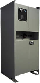
|
|
||||||||||||||||||||||||||||||||
|
||||||||||||||||||||||||||||||||
|
||||||||||||||||||||||||||||||||
|
PROTECTIONS • Overvoltage • Internal hight temperature • Overload • Short circuit • Soft start |
||||||||||||||||||||||||||||||||
|
||||||||||||||||||||||||||||||||
|
||||||||||||||||||||||||||||||||
|
EMC - Electromagnetic Compatibility D.L. 615/96 (conform to the following directives: 89/336/EEC, 92/31/EEC, 93/68/EEC and 93/97/EEC |
||||||||||||||||||||||||||||||||
|
ELECTRICAL CONNECTIONS • Input line 3000Vdc: M8 screw • Battery: connector • 380V output: connector • 220V output: connector • Input service tap: connector |
||||||||||||||||||||||||||||||||
|
LOCAL CONTROLS switch at three positions 1-0-2 • pos.1: CONNECTED • pos.0: OFF • pos.2: PREDISPOSITION TO REMOTE CONNECTION |
||||||||||||||||||||||||||||||||
|
SIGNALLING • battery input : ok • 3000Vdc input: 0k • 380V output: 0k • 220V output: ok • fault |
||||||||||||||||||||||||||||||||
- Reduce input surge at the converter;
- Reduce input voltage on the line so as not to interfere with signal circuits;
Input contactor, with relative grounding equipment, installed externally.
2) 24VDC auxiliary battery supply voltage:
It provides two stable voltages of up to 12-12VDC to supply the control logic, and an AC voltage of 70V-40kHz to supply the inverter control card.
3) Logic control:
It provides control signals to the inverter control cards, delivering an interleaved three-phase sine wave stage and stabilizing the voltage under all conditions, including load variations and voltage sags. The control logic ensures all operations related to startup and shutdown procedures and protects the equipment against input overvoltage and output overload.
4) Inverter bridge:
It is built with a Greatz-type IGBT bridge with three-phase PWM regulation at a modulation frequency of 600Hz: this value optimizes the inverter and results in a good output waveform. Isolation between the control logic and the drivers is achieved using fiber optic cable.
5) Transformer and filter capacitor:
The output voltage of the bridge is a PWM voltage interleaved in three steps. The transformer matches the value of the output voltage bridge at the value of the converted output voltage, creating input/output isolation and realizing part of the inductance of the output filter. Output filters reduce the harmonic content of the output and limit voltage deviation under step-load conditions.
6) Conversion unit result:
The converter is configured for three-phase input with a single-phase output. To protect users, two output circuit breakers are configured. The converter is equipped with a bypass switch that allows the output to be powered from an external source at 400VAC 50Hz (service point) while the unit is under maintenance.